Introduction
automesh is an open-source Rust software program that uses a segmentation,
typically generated from a 3D image stack,
or a tessellation (a triangular surface)
to create a finite element mesh.
- The volumetric elements are hexahedral, tetrahedral, hex-dominant, or polyhedral.
- The surface elements are triangular (isosurface).
automesh converts between
segmentation formats (.npy, .spn, .vti)
and
mesh formats (.exo, .inp, .mesh, .off, .stl, .vtu).
automesh can defeature voxel domains,
apply Laplacian and Taubin smoothing, with an optional hierarchical mode,
and output mesh quality metrics.
automesh can also extract a sub-range of voxels from a segmentation,
diff two segmentations to show where they differ, segment a mesh back
into a voxel domain, remesh a triangular surface with uniform or
curvature-adaptive sizing, and partition a mesh into parts written as one
.exo file per part.
Segmentation
Segmentation is the process of categorizing pixels that compose a digital image into a class that represents some subject of interest. For example, in the image below, the image pixels are classified into classes of sky, trees, cat, grass, and cow.
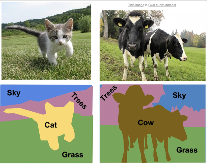
Example of semantic segmentation, from Li et al.1
- Semantic segmentation does not differentiate between objects of the same class.
- Instance segmentation does differentiate between objects of the same class.
These two concepts are shown below:
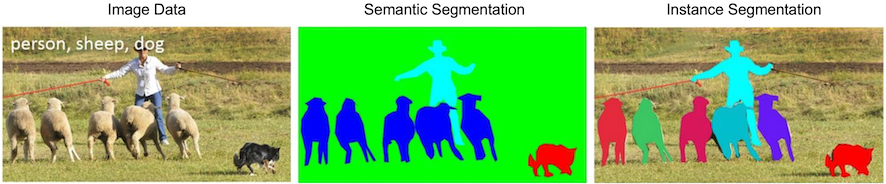
Distinction between semantic segmentation and instance segmentation, from Lin et al.2
Both segmentation types, semantic and instance, can be used with automesh. However, automesh operates on a 3D segmentation, not a 2D segmentation, as present in a digital image. To obtain a 3D segmentation, two or more images are stacked to compose a volume.
The structured volume of a stack of pixels composes a volumetric unit called a voxel. A voxel, in the context of this work, will have the same dimensionality in the x and y dimension as the pixel in the image space, and will have the z dimensionality that is the stack interval distance between each image slice. All pixels are rectangular, and all voxels are cuboid.
The figure below illustrates the concept of stacked images:
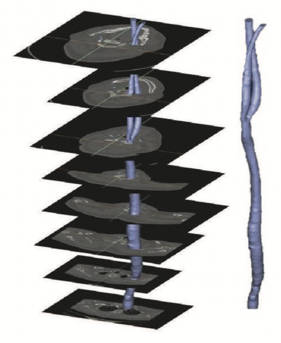
Example of stacking several images to create a 3D representation, from Bit et al.3
The digital image sources are frequently medical images, obtained by CT or MR, though automesh can be used for any subject that can be represented as a stacked segmentation. Anatomical regions are classified into categories. For example, in the image below, ten unique integers have been used to represent
bone, disc, vasculature, airway/sinus, membrane, cerebral spinal fluid, white matter, gray matter, muscle, and skin.
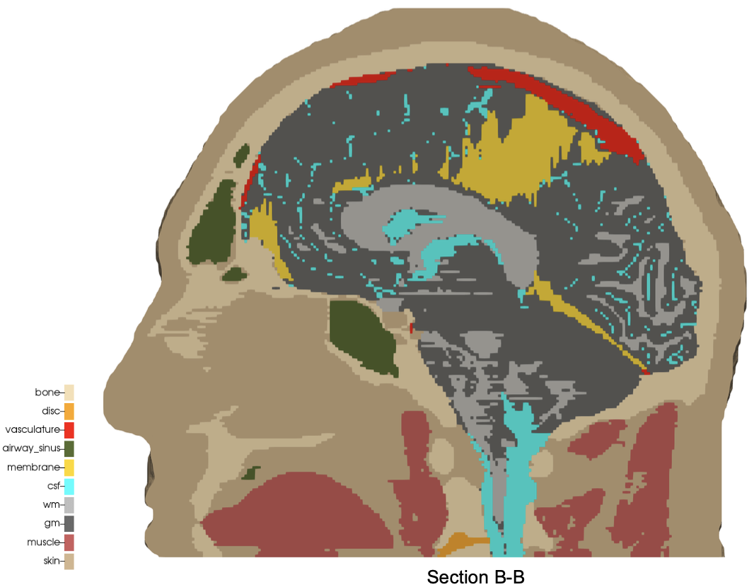
Example of a 3D voxel model, segmented into 10 categories, from Terpsma et al.4
Given a 3D segmentation, for any image slice that composes it, the pixels have been classified
into categories that are designated with unique, non-negative integers.
The range of integer values is limited to 256 = 2^8, since the uint8 data type is specified.
A practical example of a range could be [0, 1, 2, 3, 4]. The integers do not need to be sequential,
so a range of [4, 501, 2, 0, 42] is also valid, but not conventional.
Segmentations are frequently serialized (saved to disc) as either a NumPy (.npy) file
or a SPN (.spn) file.
A SPN file is a text (human-readable) file that contains a single column of non-negative integer values. Each integer value defines a unique category of a segmentation.
Axis order (for example,
x, y, then z; or, z, y, x, etc.) is not implied by the SPN structure;
so additional data is needed to uniquely interpret the pixel tile and voxel
stack order of the data in the SPN file. automesh takes this as the
--nelx, --nely, and --nelz command line arguments.
For subjects that are human anatomy, we use the Patient Coordinate System (PCS), which directs the
x, y, and z axes to the left, posterior, and superior, as shown below:
| Patient Coordinate System: | Left, Posterior, Superior (x, y, z) |
|---|---|
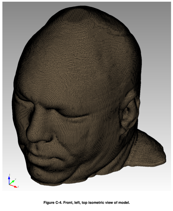 | 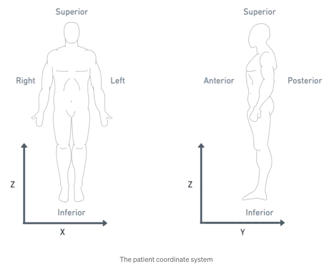 |
Illustration of the patient coordinate system, left figure from Terpsma et al.4 and right figure from Sharma.5
Mesh
automesh writes several mesh formats: .exo, the EXODUS II finite element
data model;6 .inp, the Abaqus input format;7 .mesh,
the Medit format;8 .off, the Object File Format used by
Geomview;9 .stl, the STL format for triangular surfaces in
3D;10 and .vtu, the VTK XML UnstructuredGrid
format.11
References
-
Li FF, Johnson J, Yeung S. Lecture 11: Detection and Segmentation, CS 231n, Stanford University, 2017. link ↩
-
Lin TY, Maire M, Belongie S, Hays J, Perona P, Ramanan D, Dollár P, Zitnick CL. Microsoft coco: Common objects in context. In Computer Vision–ECCV 2014: 13th European Conference, Zurich, Switzerland, September 6-12, 2014, Proceedings, Part V 13 2014 (pp. 740-755). Springer International Publishing. link ↩
-
Bit A, Ghagare D, Rizvanov AA, Chattopadhyay H. Assessment of influences of stenoses in right carotid artery on left carotid artery using wall stress marker. BioMed research international. 2017;2017(1):2935195. link ↩
-
Terpsma RJ, Hovey CB. Blunt impact brain injury using cellular injury criterion. Sandia National Lab. (SNL-NM), Albuquerque, NM (United States); 2020 Oct 1. link ↩ ↩2
-
Sharma S. DICOM Coordinate Systems — 3D DICOM for computer vision engineers, Medium, 2021-12-22. link ↩
-
Schoof LA, Yarberry VR. EXODUS II: a finite element data model. Sandia National Lab. (SNL-NM), Albuquerque, NM (United States); 1994 Sep 1. link ↩
-
Dassault Systèmes Simulia Corp. Abaqus documentation. link ↩
-
Frey PJ. MEDIT: an interactive mesh visualization software. Institut National de Recherche en Informatique et en Automatique (INRIA); 2001 Dec. Technical Report RT-0253. link ↩
-
Phillips M, Levy S, Munzner T. Geomview: An interactive geometry viewer. Notices of the American Mathematical Society. 1993 Oct;40:985-8. See also: Phillips M, et al. Geomview Manual, Geomview version 1.9 for Unix. 2007 Apr. link ↩
-
3D Systems Inc. StereoLithography Interface Specification. 1989 Oct. See also: Library of Congress. STL (StereoLithography) File Format Family, Sustainability of Digital Formats, fdd000504. link ↩