Simulation
Work in progress.
Meshes
Copy from local to HPC:
# for example, manual copy from local to HPC
# macOS local finder, command+K to launch "Connect to Server"
# smb://cee/chovey
# copy [local]~/autotwin/automesh/book/analysis/sphere_with_shells/spheres_resolution_2.exo
# to
# [HPC]~/autotwin/ssm/geometry/sr2/
We consider three simulations using the following three meshes (in the HPC ~/autotwin/ssm/geometry folder):
| folder | file | md5 checksum |
|---|---|---|
sr2 | spheres_resolution_2.exo | 9f40c8bd91874f87e22a456c76b4448c |
sr3 | spheres_resolution_3.exo | 6ae69132897577e526860515e53c9018 |
sr4 | spheres_resolution_4.exo | b939bc65ce07d3ac6a573a4f1178cfd0 |
We do not use the spheres_resolution_1.exo because the outer shell layer is not closed.
Boundary Conditions
Consider an angular acceleration pulse of the form:
and is zero otherwise. This pulse, referred to as the bump function, is continuously differentiable, with peak angular acceleration at .
With krad/s^2, and ms, we can create the angular acceleration boundary condition (with corresponding angular velocity) 1 plots:
| Angular Acceleration | Angular Velocity |
|---|---|
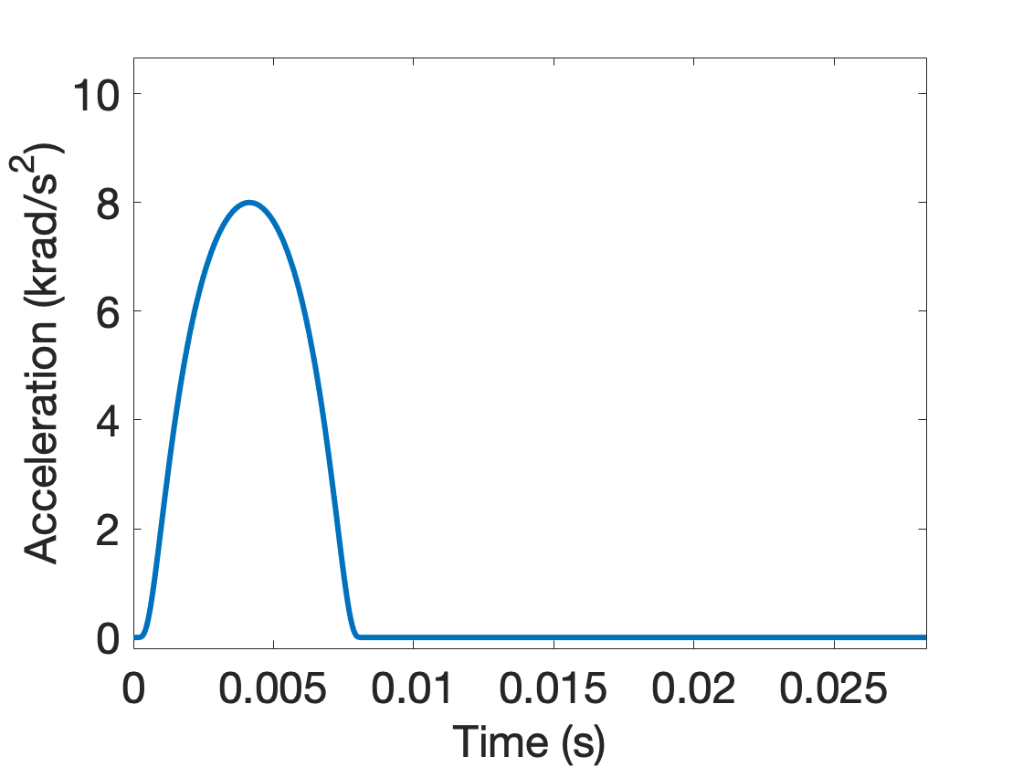 |  |
Figure: Angular acceleration and corresponding angular velocity time history.
- Angular acceleration tabulated data: The standardized angular acceleration load curve has column data as (time, magnitude) in (sec, krad/s^2). The function used to generated the curve, from Equation (1) of 1, is
- Angular velocity tabulated data: The angular velocity curve has column data as (time, magnitude) in (sec, rad/s).
The peak angular acceleration ocurrs at (which occurs in the tabular data at data point 4144, values (0.00414310, 7.99999997)).
On the outer shell (block 3) of the model, we prescribe the angular velocity boundary condition.
Tracers
View the tracer locations in Cubit:
graphics clip on plane location 0 0 1 direction 0 0 -1
view up 0 1 0
view from 0 0 100
graphics clip manipulation off
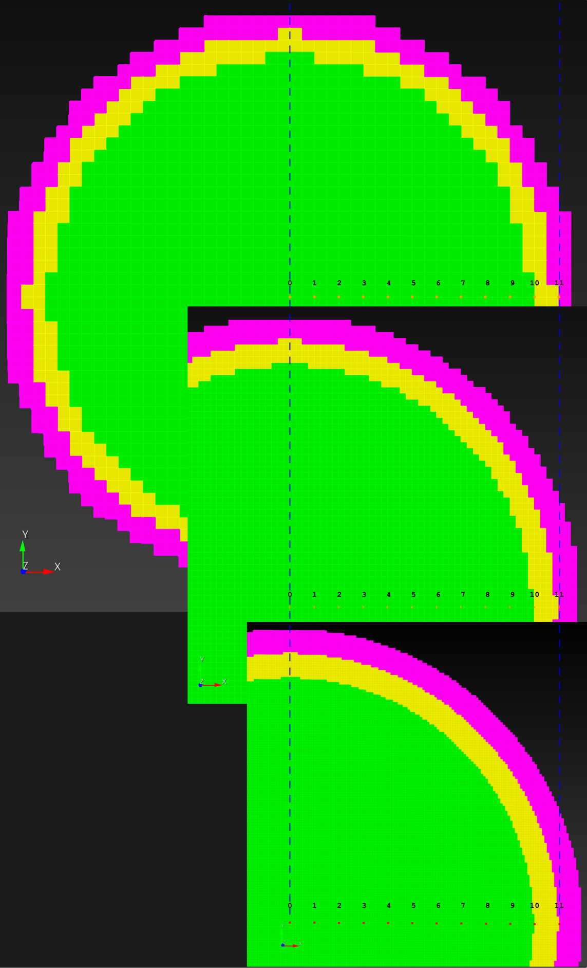
Figure: Tracer numbers [0, 1, 2, ... 11] at distance [0, 1, 2, ... 11] centimeters from point (0, 0, 0) along the x-axis at resolutions sr2, sr3, and sr4 (top to bottom, respectively).
Materials
We model the outer shell (block 3) as a rigid body. The inner sphere (block 1) is nodeled as Swanson viscoelastic white matter. The intermediate material (block 2) is modeled as elastic cerebral spinal fluid.
Input deck
We created three input decks:
sr2.i(for meshspheres_reolution_2.exo)sr3.i(for meshspheres_reolution_3.exo)sr4.i(for meshspheres_reolution_4.exo)
Remark: Originally, we used APREPRO, part of SEACAS, to define tracer points along the line at 1-cm (radial) intervals. We then updated the locations of these tracer points to be along the x-axis, which allowed for nodally exact locations to be established across all models, voxelized and conforming.
Displacement, maximum principal log strain, and maximum principal rate of deformation were logged at tracer points over the simulation duration. The Sierra/Solid Mechanics documentation 2 3 was also useful for creating the input decks.
Solver
Request resources:
mywcid # see what wcid resources are available, gives an FYxxxxxx number
#request 1 interactive node for four hours with wcid account FY180100
salloc -N1 --time=4:00:00 --account=FY180100
See idle nodes:
sinfo
Decompose the geometry, e.g., ~/autotwin/ssm/geometry/sr2/submit_script:
#!/bin/bash

module purge
module load sierra
module load seacas

# previously ran with 16 processors
# PROCS=16
# 10 nodes = 160 processors
PROCS=160
# PROCS=320
# PROCS=336

# geometry and mesh file
GFILE="spheres_resolution_2.exo"

decomp --processors $PROCS $GFILE
Check the input deck ~/autotwin/ssm/input/sr2/sr2.i with submit_check:
#!/bin/bash

echo "This is submit_check"
echo "module purge"
module purge

echo "module load sierra"
module load sierra

# new, run this first
export PSM2_DEVICES='shm,self'

IFILE="sr2.i"

echo "Check syntax of input deck: $IFILE"
adagio --check-syntax -i $IFILE  # to check syntax of input deck

# echo "Check syntax of input deck ($IFILE) and mesh loading"
adagio --check-input  -i $IFILE  # to check syntax of input deck and mesh load
Clean any preexisting result files with submit_clean:
#!/bin/bash

echo "This is submit_clean"
rm batch_*
rm sierra_batch_*
rm *.e.*
rm epu.log
rm *.g.*
rm *.err
rm g.rsout.*
Submit the job with submit_script:
#!/bin/bash

echo "This is submit_script"
module purge
module load sierra
module load seacas

# PROCS=16
PROCS=160
# PROCS=320
# PROCS=336

# geometry and mesh file
# GFILE="../../geometry/sphere/spheres_resolution_4.exo"
# decomp --processors $PROCS $GFILE

IFILE="sr2.i"

# queues
# https://wiki.sandia.gov/pages/viewpage.action?pageId=1359570410#SlurmDocumentation-Queues
# short can be used for nodes <= 40 and wall time <= 4:00:00 (4 hours)
# batch, the default queue, wall time <= 48 h
# long, wall time <= 96 h, eclipse 256 nodes

# https://wiki.sandia.gov/display/OK/Slurm+Documentation
# over 4 hours, then need to remove 'short' from the --queue-name
#
# sierra -T 00:20:00 --queue-name batch,short --account FY180042 -j $PROCS --job-name $IFILE --run adagio -i $IFILE
sierra -T 04:00:00 --queue-name batch,short --account FY180042 -j $PROCS --job-name $IFILE --run adagio -i $IFILE
# sierra -T 06:00:00 --queue-name batch --account FY180042 -j $PROCS --job-name $IFILE --run adagio -i $IFILE
# sierra -T 24:00:00 --queue-name batch --account FY180042 -j $PROCS --job-name $IFILE --run adagio -i $IFILE
Monitor the job:
# monitoring
squeue -u chovey
tail foo.log
tail -f foo.log # interactive monitor
Add shortcuts, if desired, to the ~/.bash_profile:
alias sq="squeue -u chovey"
alias ss="squeue -u chovey --start"
Cancel the job:
scancel JOB_ID
scancel -u chovey # cancel all jobs
Compute time:
| item | sim | T_sim (ms) | HPC | #proc | cpu time (hh:mm) |
|---|---|---|---|---|---|
| 0 | sr2.i | 20 | att | 160 | less than 1 min |
| 1 | sr3.i | 20 | att | 160 | 00:04 |
| 2 | sr4.i | 20 | ecl | 160 | 03:58 |
Results
Copy the files, history_rigid.csv and history.csv, which contain tracer rigid and deformable body time histories, from the HPC to the local.
Rigid Body
With figio and the rigid_body_ang_kinematics.yml recipe,
cd ~/autotwin/automesh/book/analysis/sphere_with_shells/recipes
figio rigid_body_ang_kinematics.yml
verify that the rigid body input values were sucessfully reflected in the output:
| angular acceleration | angular velocity | angular position |
|---|---|---|
Figure: Rigid body (block 3) kinematics for sr2, the sphere_resolution_2.exo model. The time history traces appear the same for the sr3 and sr4 models.
Deformable Body
The following figure shows the maximum principal log strain for various resolutions and selected times.
| resolution | 2 vox/cm | 4 vox/cm | 10 vox/cm |
|---|---|---|---|
| midline | 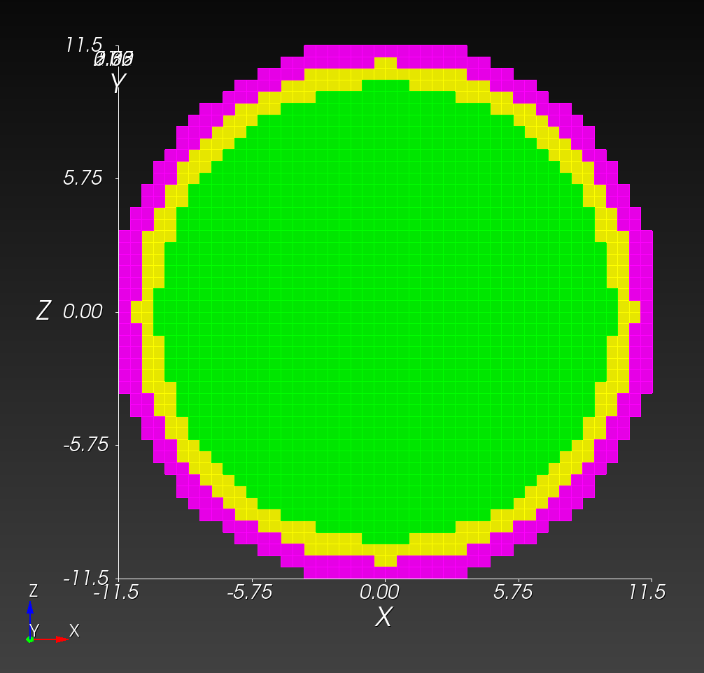 | 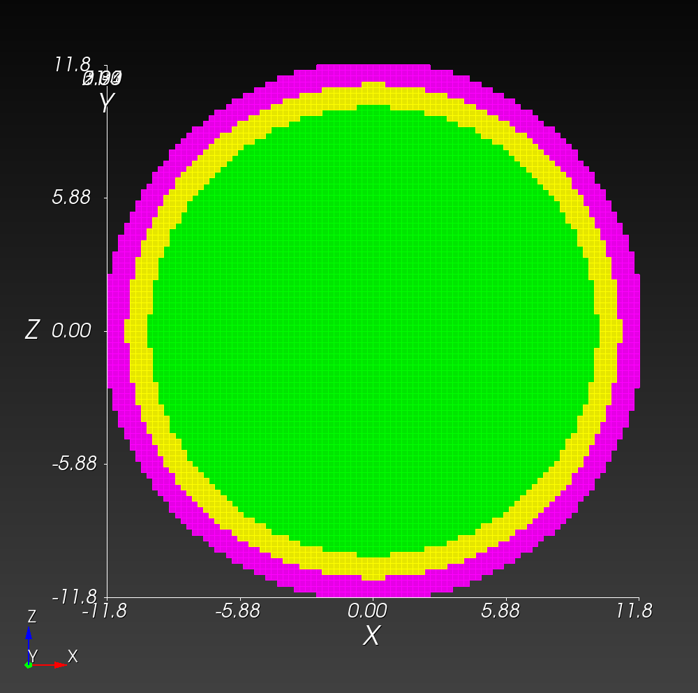 | 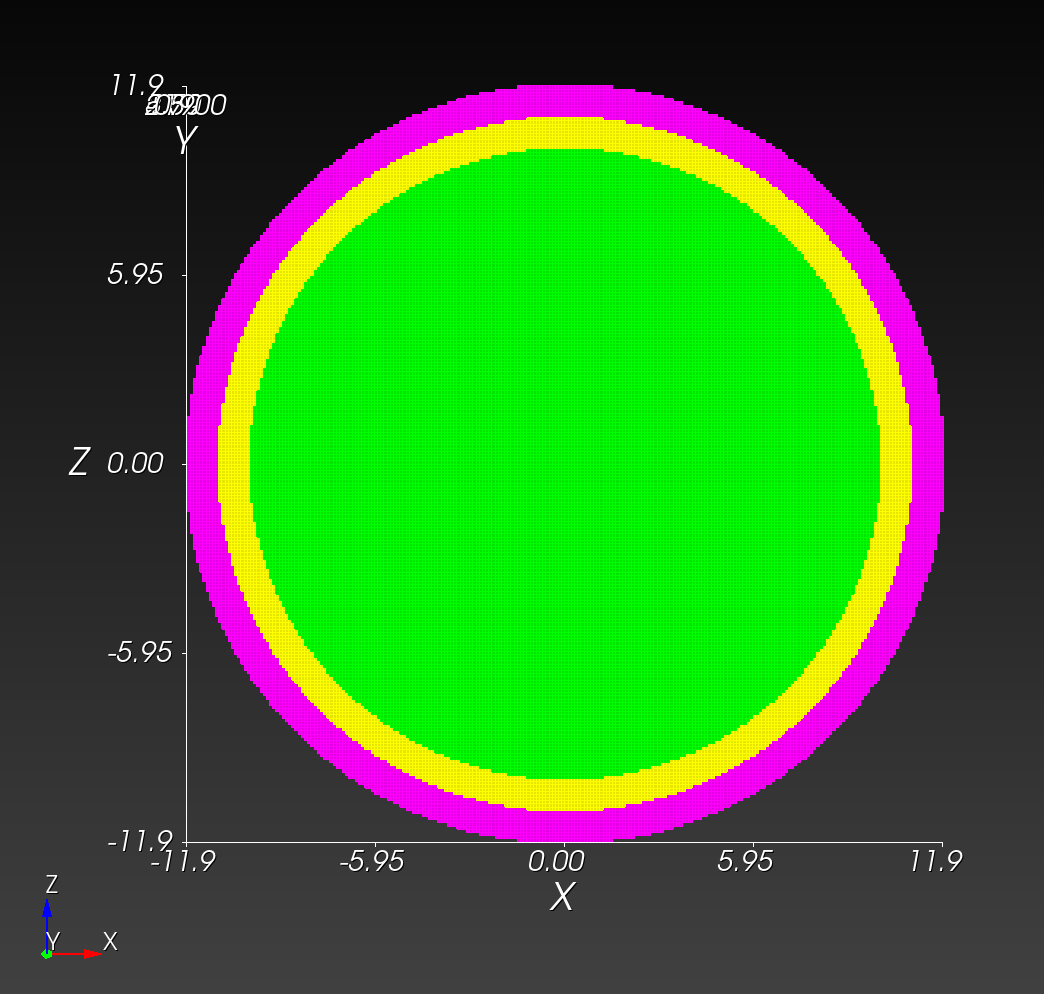 |
| t=0.000 s | 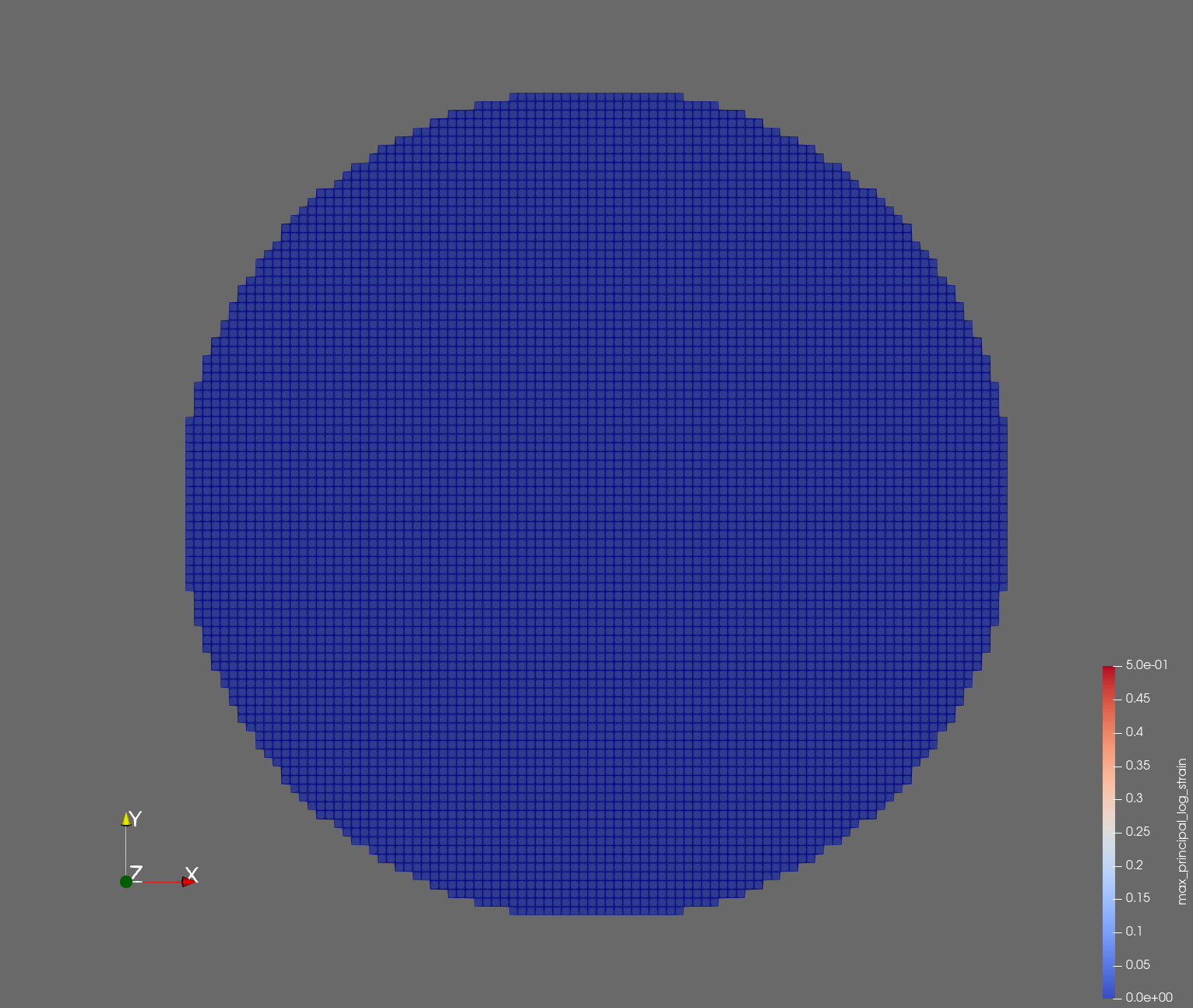 |  |  |
| t=0.002 s | 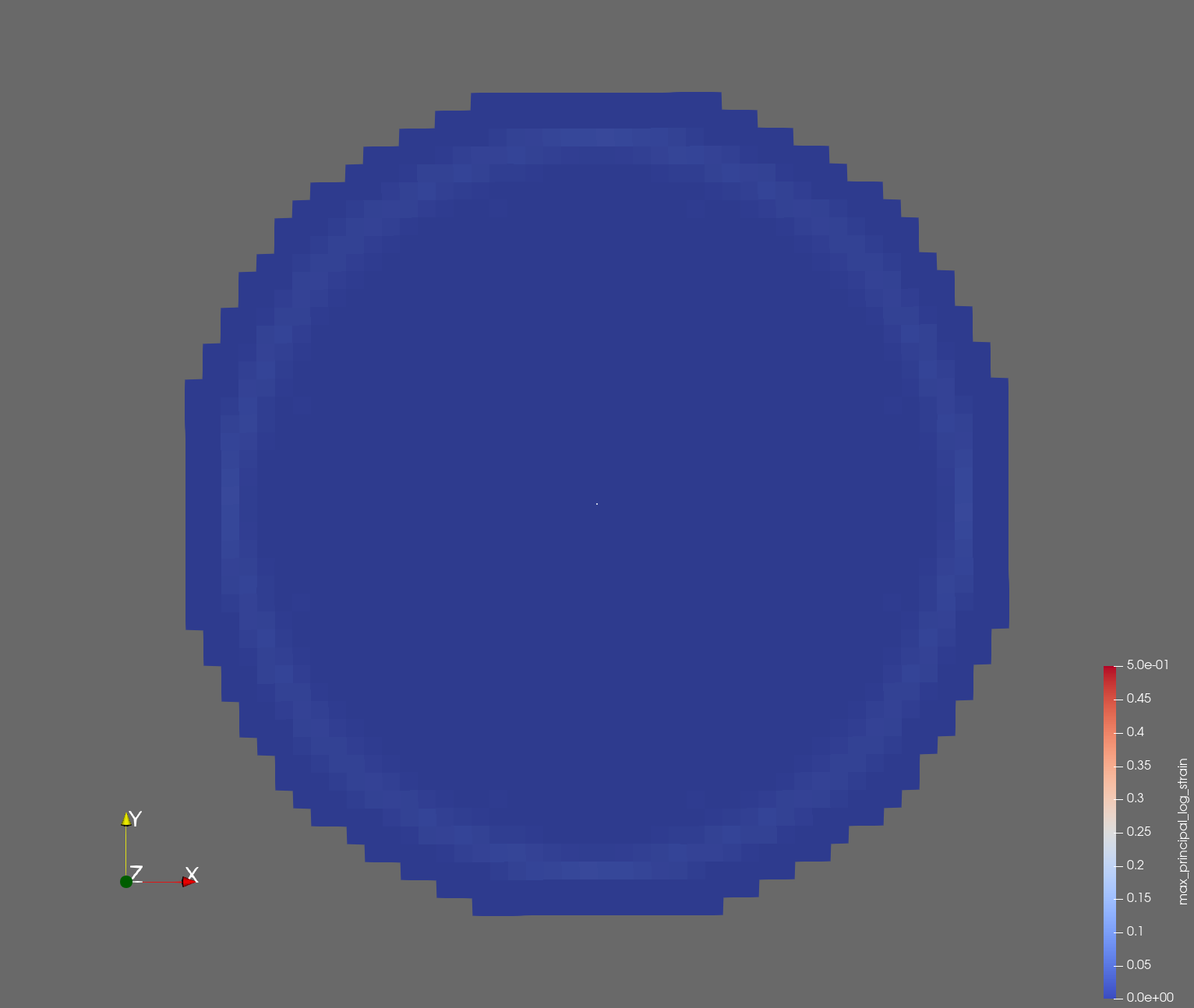 | 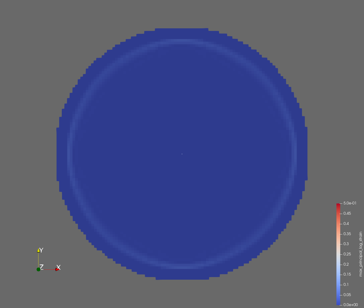 |  |
| t=0.004 s | 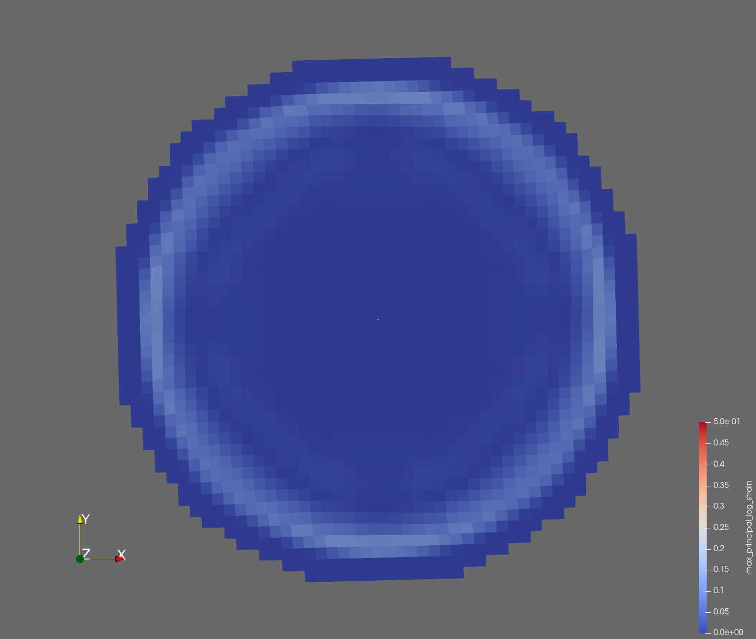 | 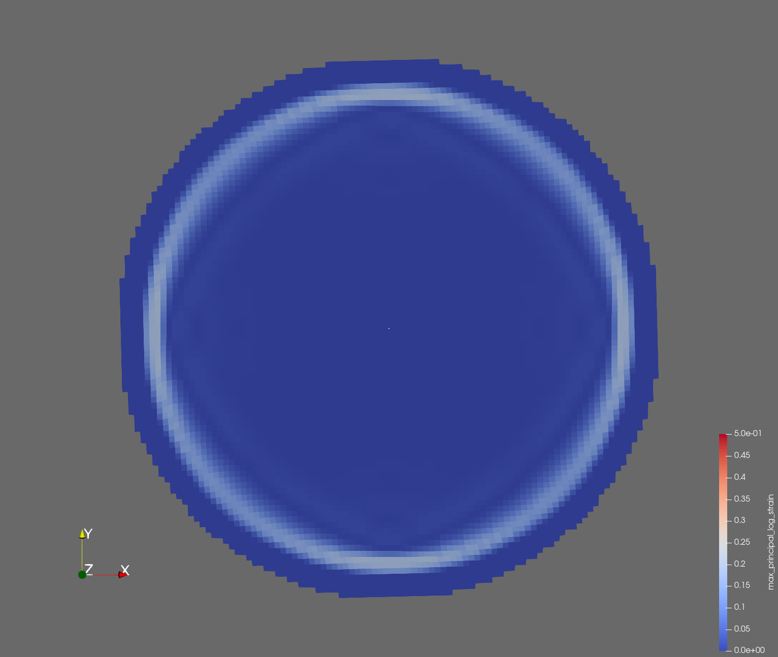 |  |
| t=0.006 s | 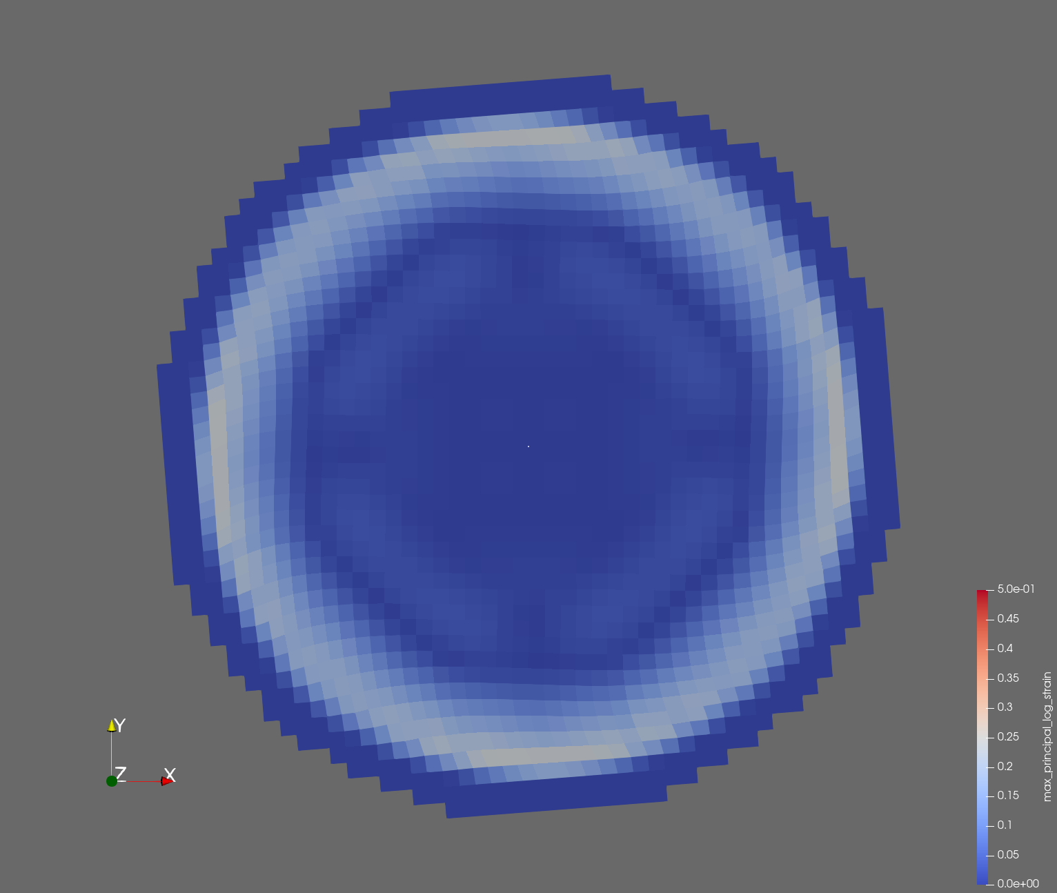 | 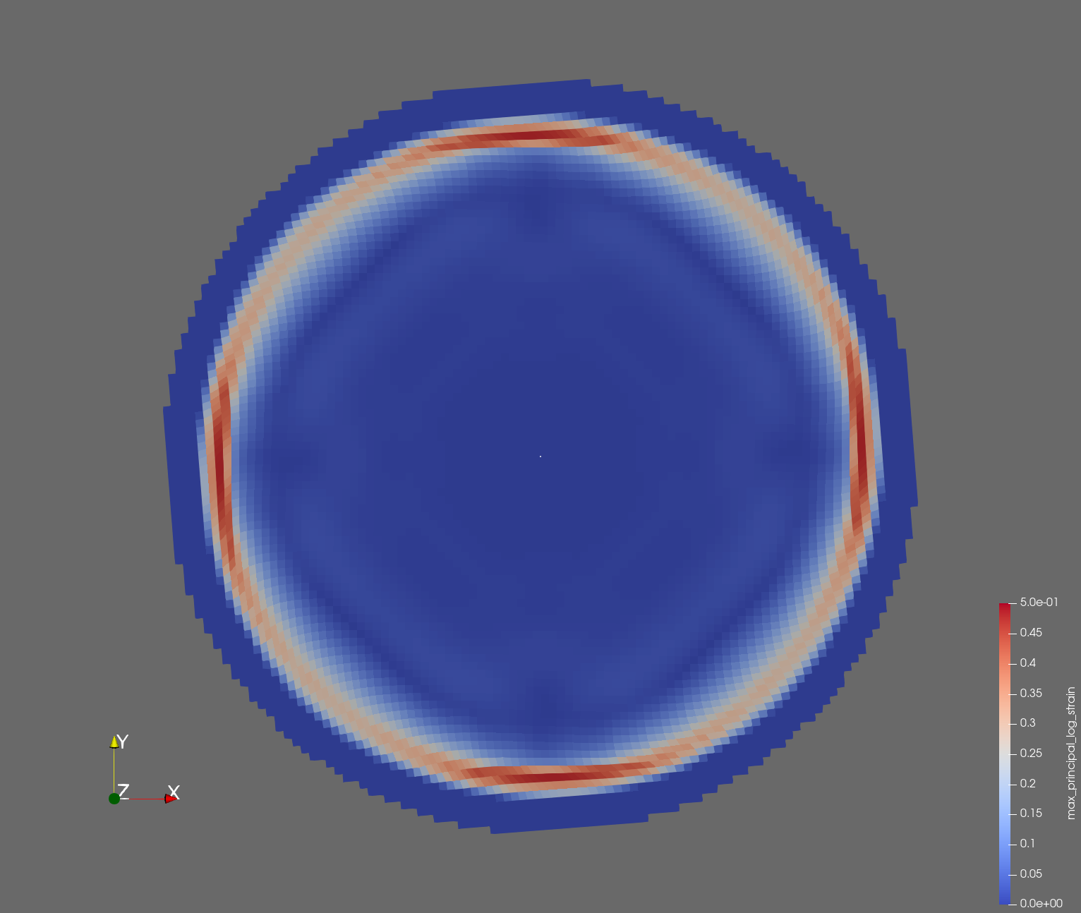 |  |
| t=0.008 s | 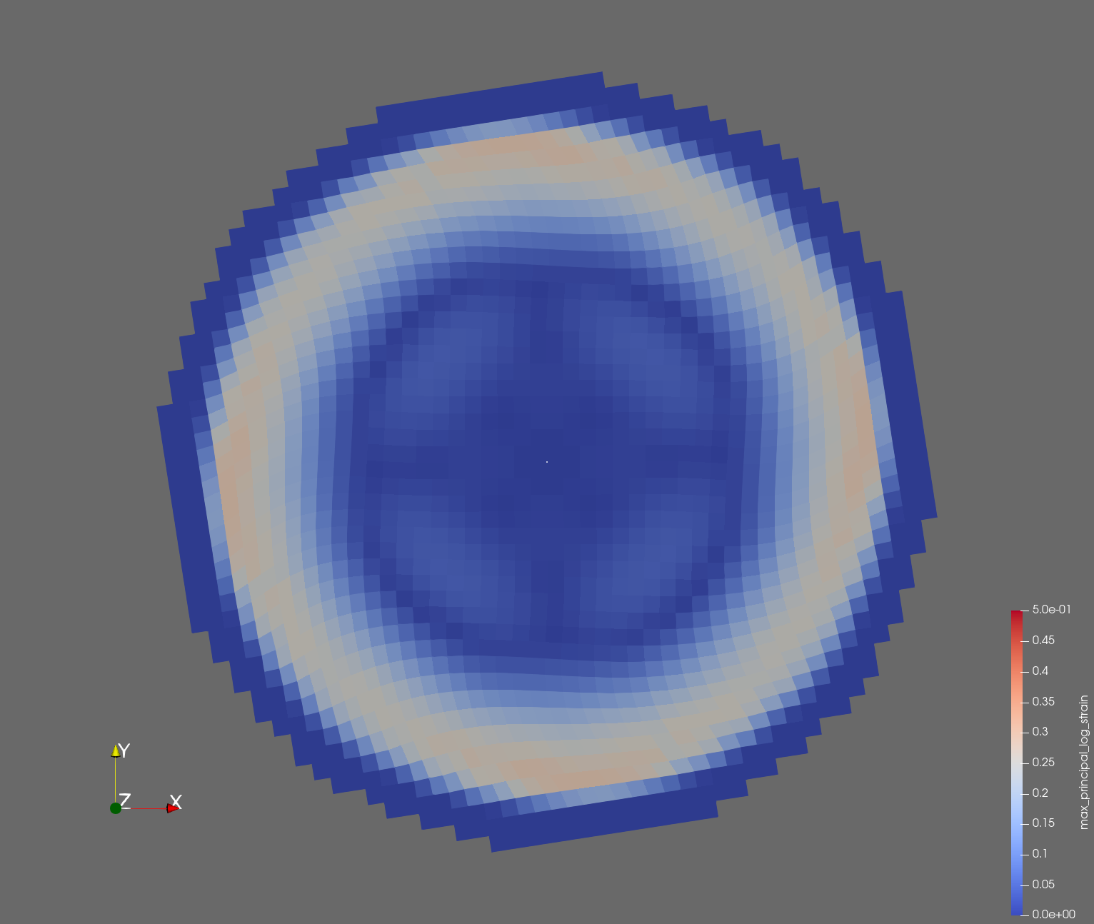 | 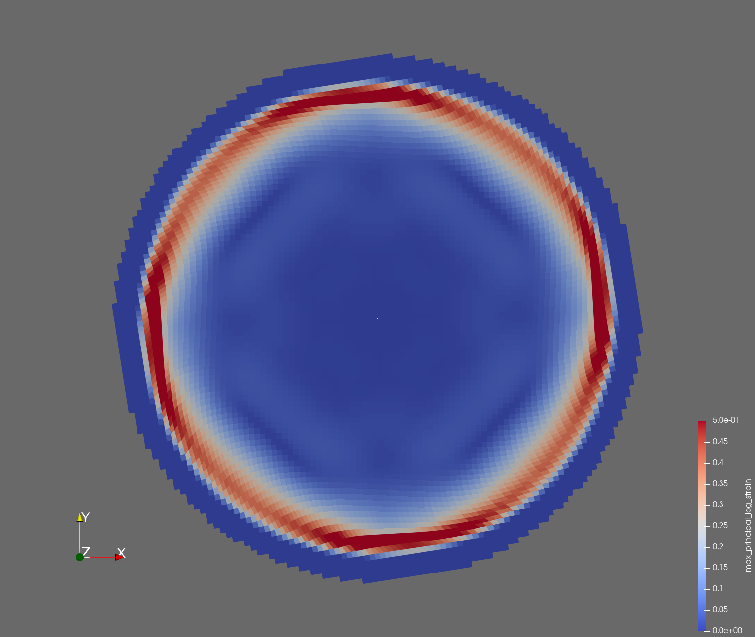 |  |
| t=0.010 s | 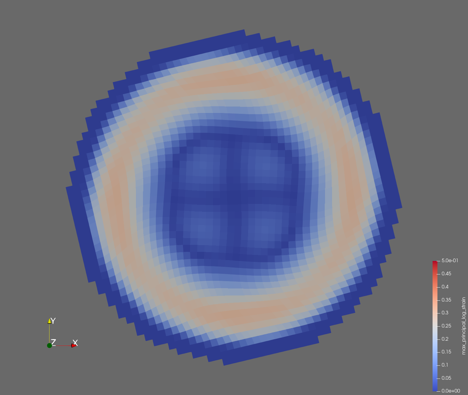 | 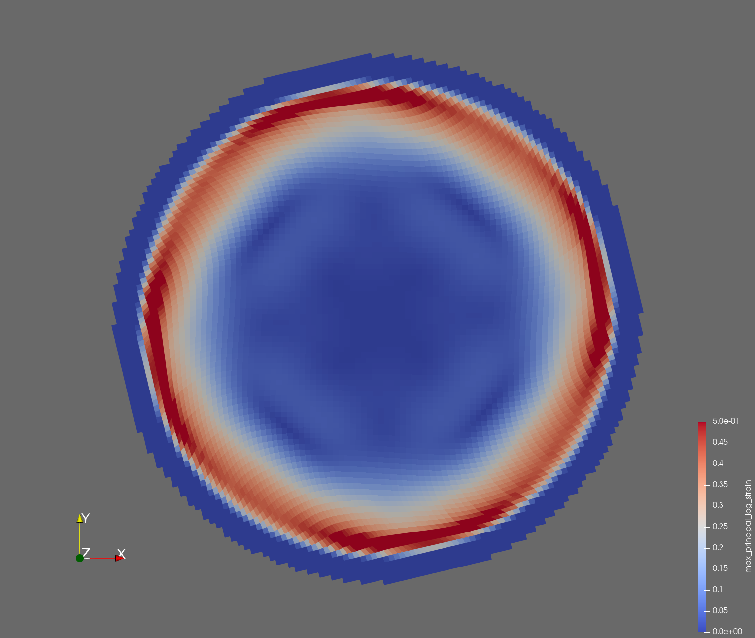 |  |
| t=0.012 s | 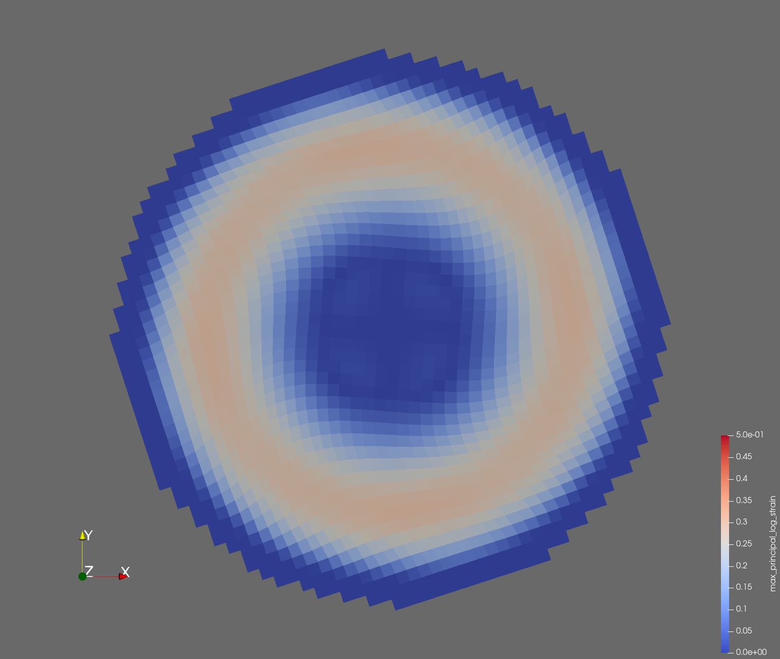 | 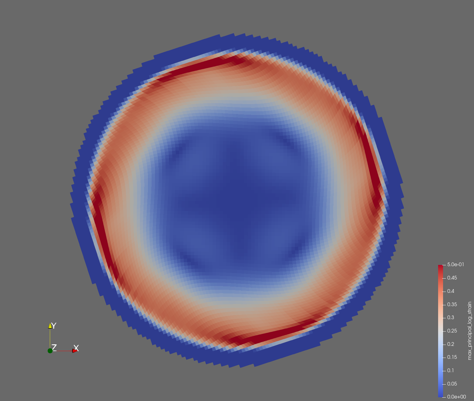 |  |
| t=0.014 s | 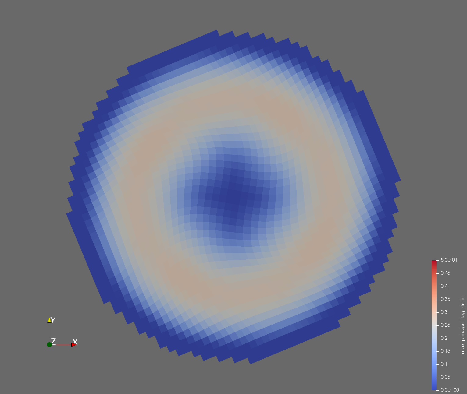 | 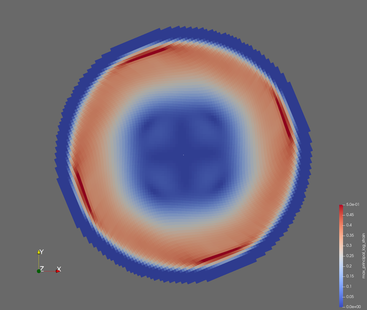 |  |
| t=0.016 s | 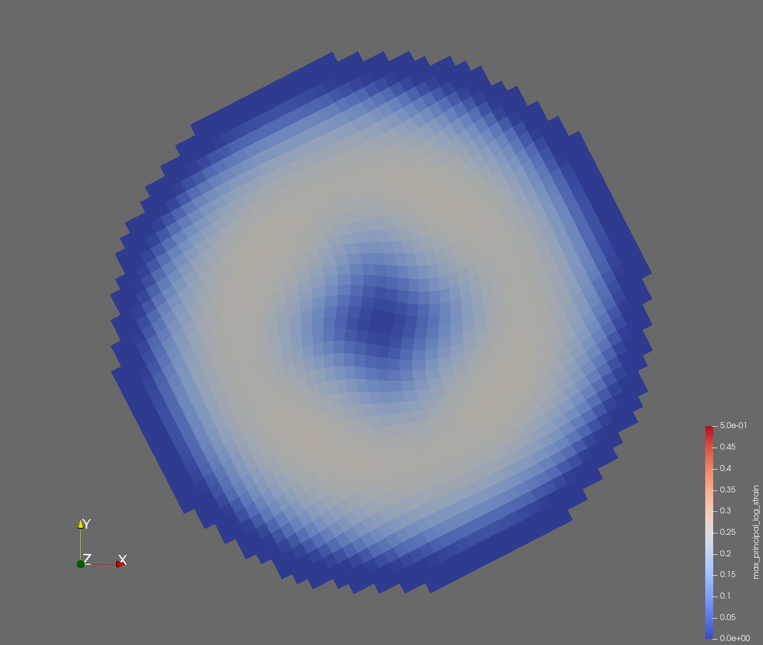 | 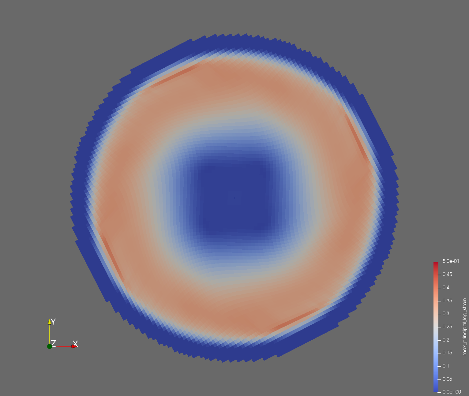 |  |
| t=0.018 s | 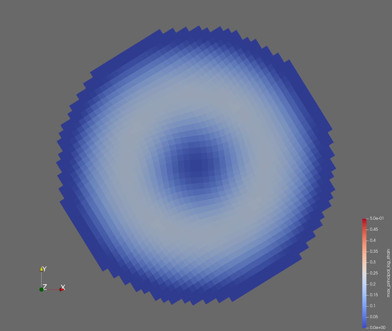 | 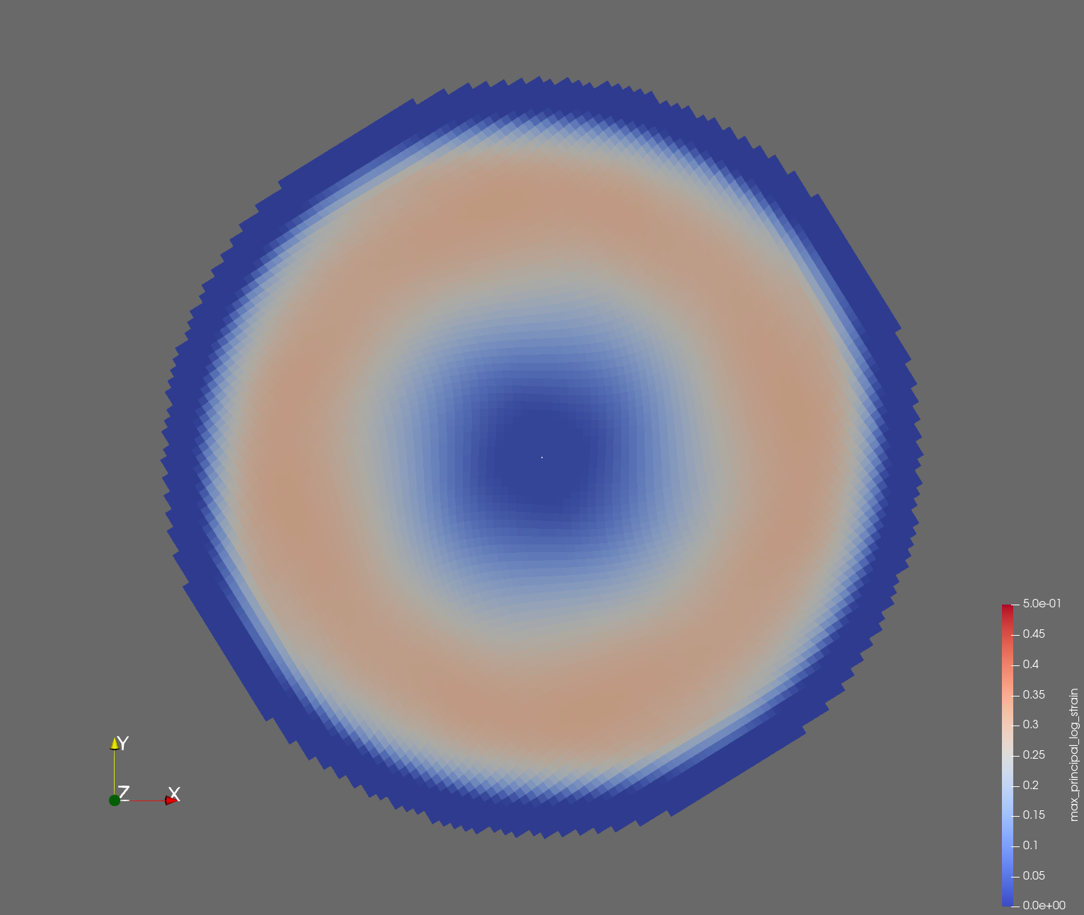 |  |
| t=0.020 s | 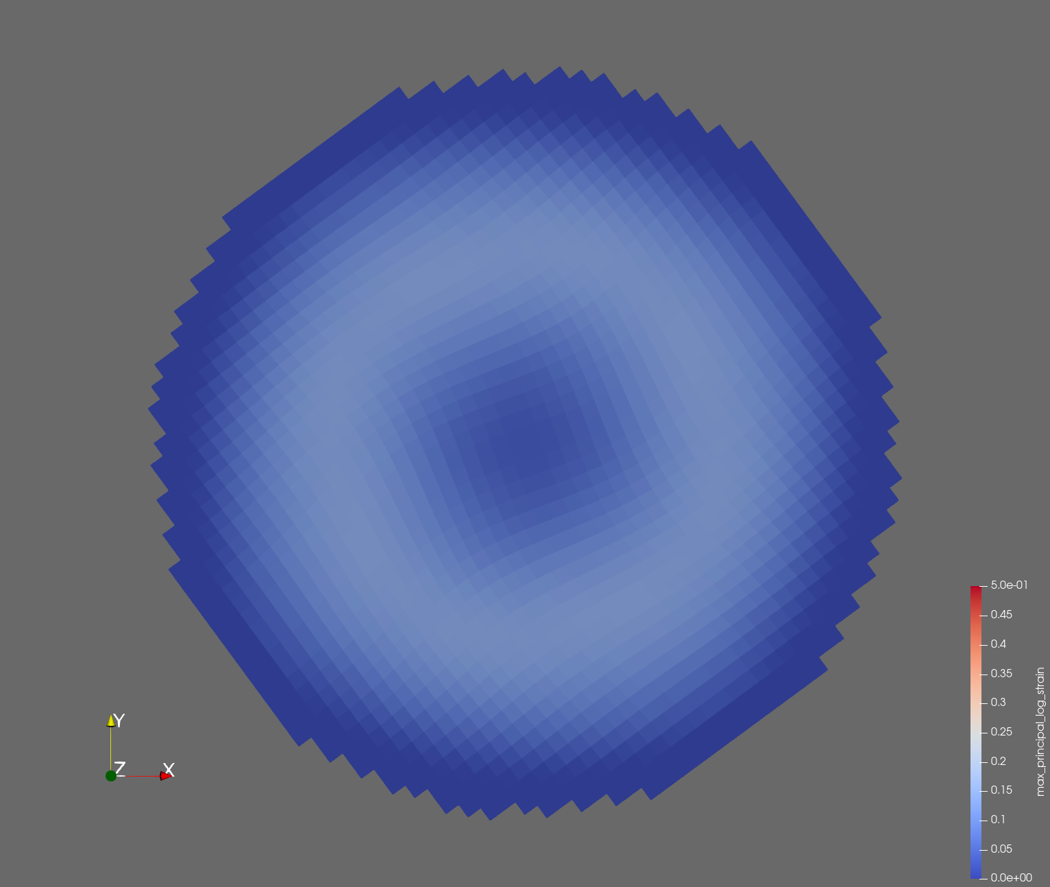 | 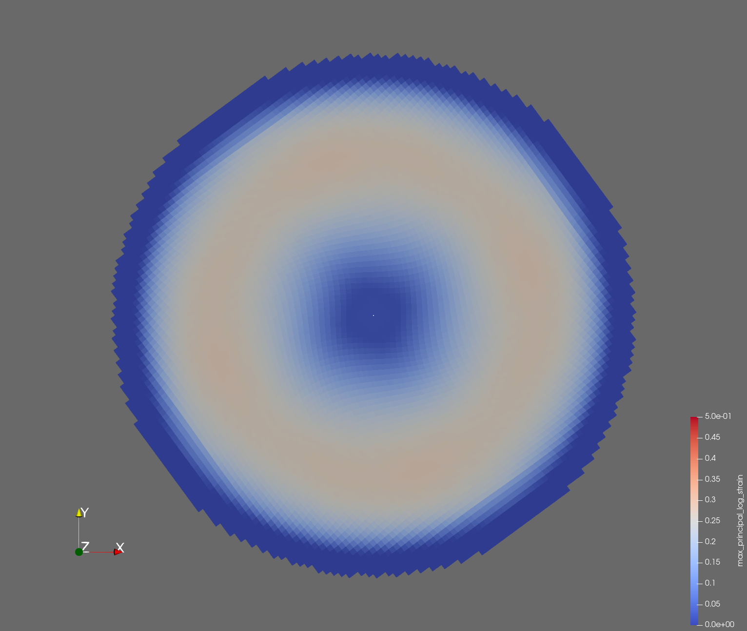 |  |
| displacement | |||
| recipe | displacement_sr2.yml | displacement_sr3.yml | displacement_sr4.yml |
| log strain | |||
| recipe | log_strain_sr2.yml | log_strain_sr3.yml | log_strain_sr4.yml |
| rate of deformation | |||
| recipe | rate_of_deformation_sr2.yml | rate_of_deformation_sr3.yml | rate_of_deformation_sr4.yml |
Figure: Voxel mesh midline section, with contour plot of maximum principal log strain at selected times from 0.000 s to 0.020 s (1,000 Hz sample rate, = 0.001 s), and tracer plots at 1 cm interval along the -axis for displacement magnitude, log strain, and rate of deformation (4,000 Hz acquisition rate, = 0.00025 s).
References
-
Carlsen RW, Fawzi AL, Wan Y, Kesari H, Franck C. A quantitative relationship between rotational head kinematics and brain tissue strain from a 2-D parametric finite element analysis. Brain Multiphysics. 2021 Jan 1;2:100024. paper ↩ ↩2
-
Beckwith FN, Bergel GL, de Frias GJ, Manktelow KL, Merewether MT, Miller ST, Parmar KJ, Shelton TR, Thomas JD, Trageser J, Treweek BC. Sierra/SolidMechanics 5.10 Theory Manual. Sandia National Lab. (SNL-NM), Albuquerque, NM (United States); Sandia National Lab. (SNL-CA), Livermore, CA (United States); 2022 Sep 1. link ↩
-
Thomas JD, Beckwith F, Buche MR, de Frias GJ, Gampert SO, Manktelow K, Merewether MT, Miller ST, Mosby MD, Parmar KJ, Rand MG, Schlinkman RT, Shelton TR, Trageser J, Treweek B, Veilleux MG, Wagman EB. Sierra/SolidMechanics 5.22 Example Problems Manual. Sandia National Lab. (SNL-NM), Albuquerque, NM (United States); Sandia National Lab. (SNL-CA), Livermore, CA (United States); 2024 Oct 1. link ↩