Conforming Mesh
In this section, we develop a traditional conforming mesh, manually constructed with Cubit. We compare the results from the conforming resolutions to the results obtained from the voxel mesh resolutions.
Mesh Creation and Visualization
With conforming_spheres.jou in Cubit, we create three conforming meshes to match the three voxel meshes of resolution 0.5, 0.25, and 0.1 cm (2 vox/cm, 4 vox/cm, and 10 vox/cm, respectively).
| resolution | 2 vox/cm | 4 vox/cm | 10 vox/cm |
|---|---|---|---|
| midline | 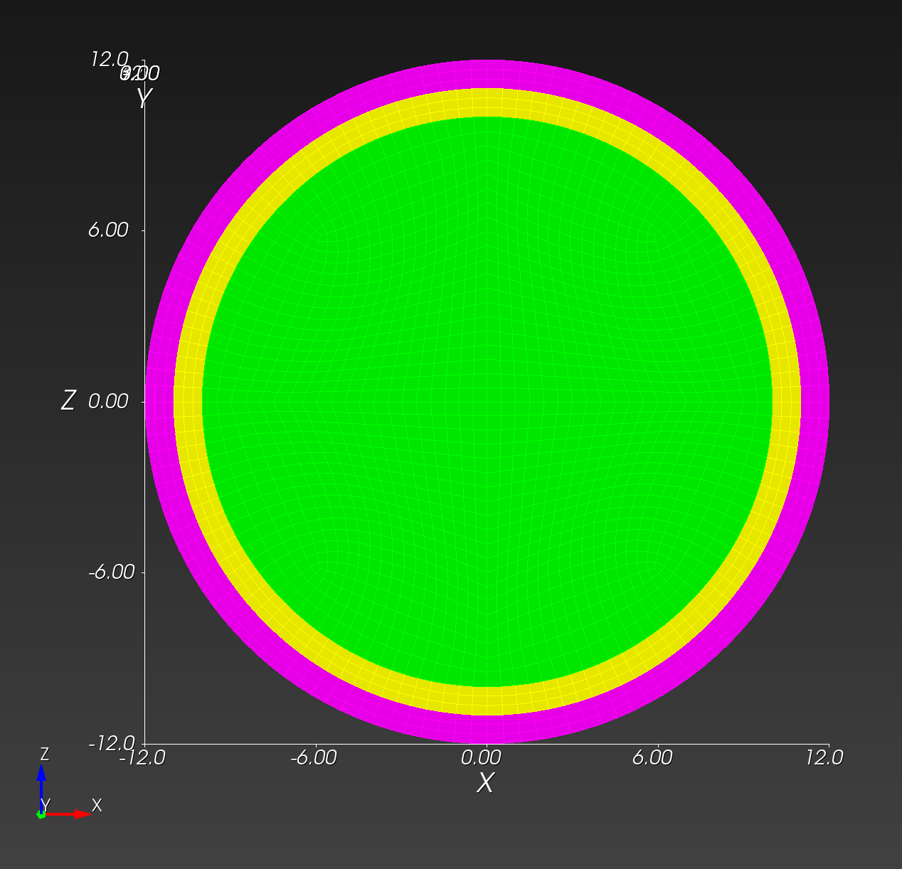 | 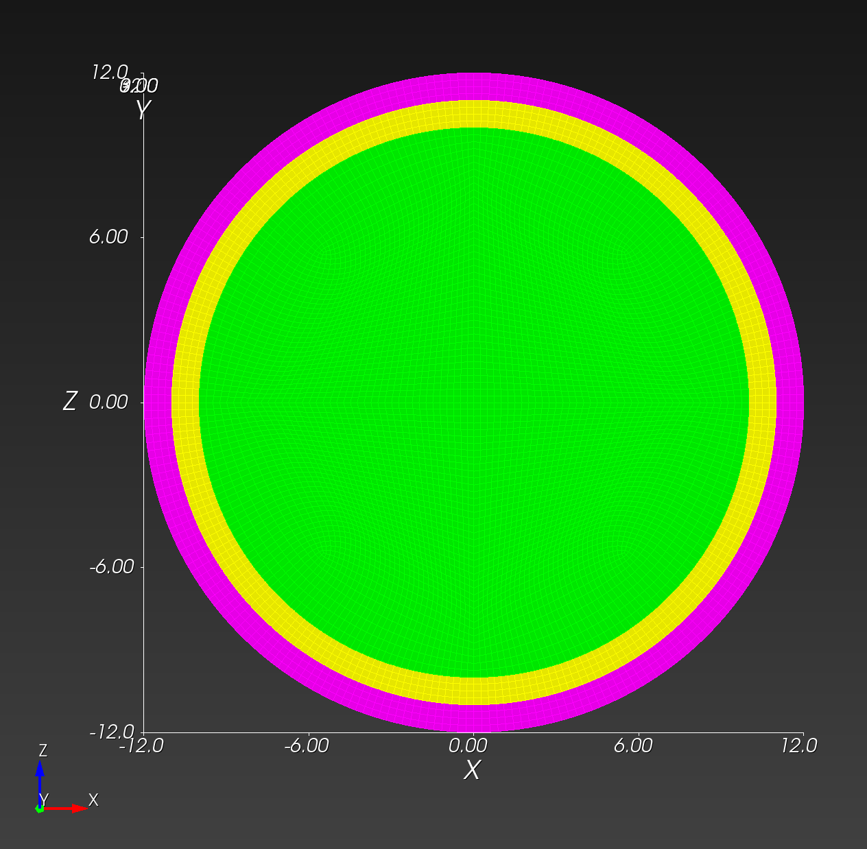 | 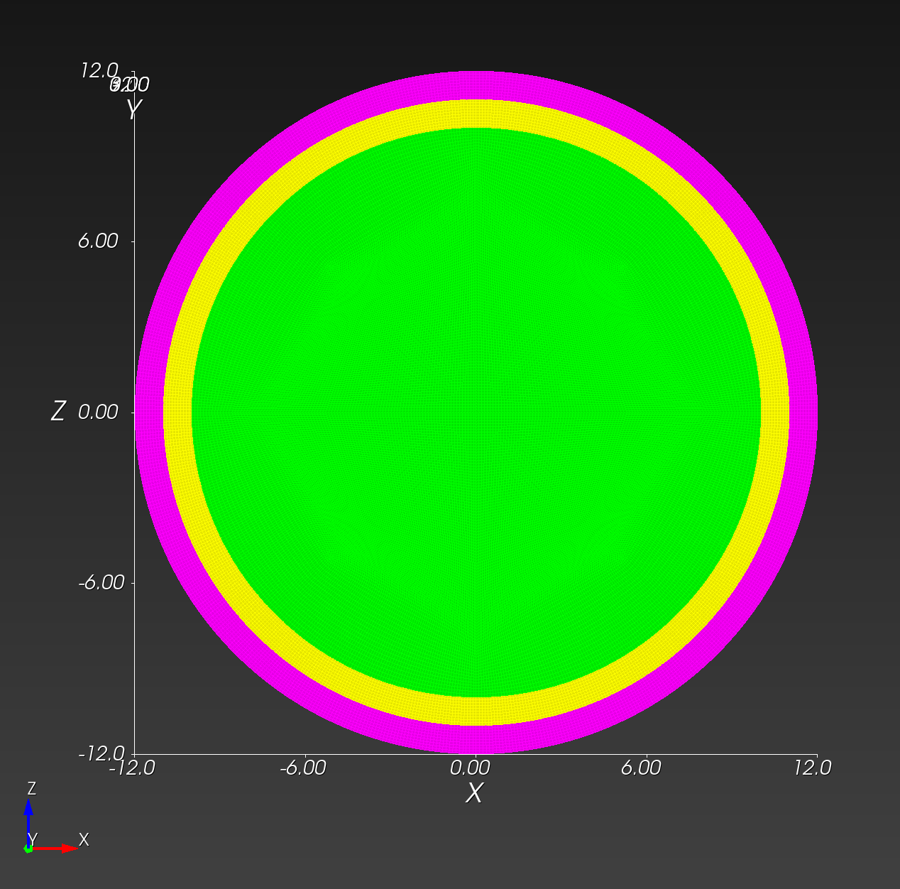 |
| isometric | 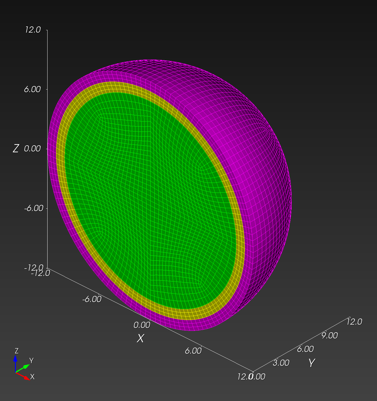 | 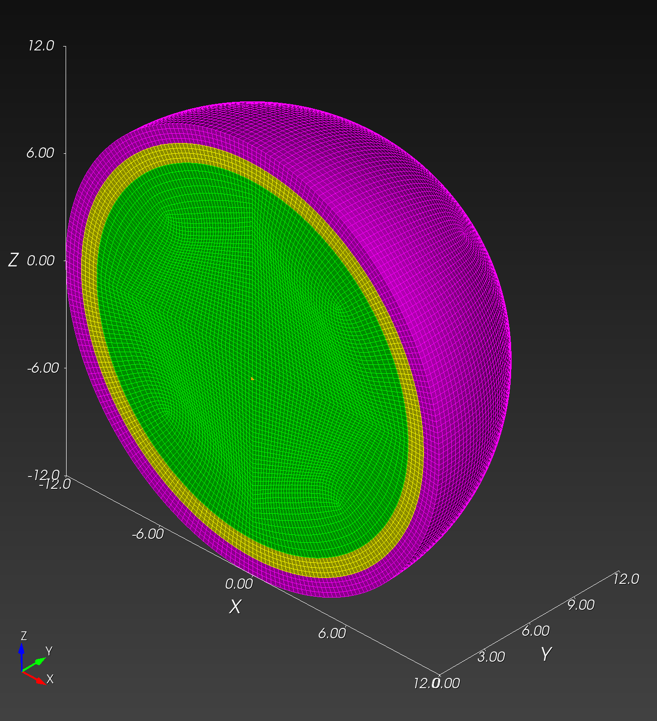 | 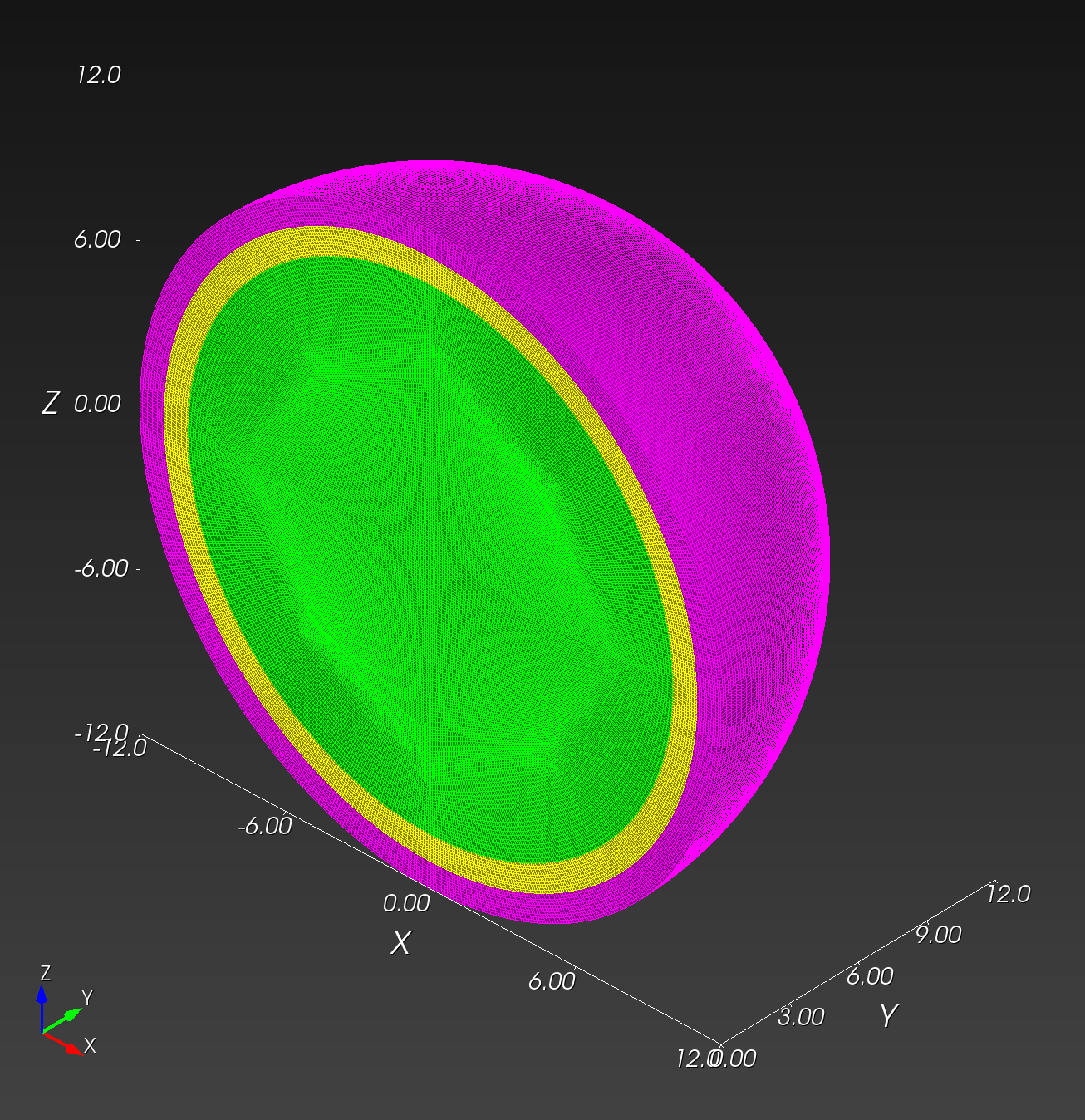 |
| block 1 (green) #elements | 57,344 | 458,752 | 7,089,776 |
| block 2 (yellow) #elements | 18,432 | 98,304 | 1,497,840 |
| block 3 (magenta) #elements | 18,432 | 98,304 | 1,497,840 |
| total #elements | 94,208 | 655,360 | 10,085,456 |
Copy from local to HPC:
# for example, manual copy from local to HPC
# macOS local finder, command+K to launch "Connect to Server"
# smb://cee/chovey
# copy [local]~/autotwin/automesh/book/analysis/sphere_with_shells/conf_0.5cm.g
# to
# [HPC]~/autotwin/ssm/geometry/sr2c/
We consider three simulations using the following three meshes (in the HPC ~/autotwin/ssm/geometry folder or downloadable from the links in the file column below):
| folder | file | md5 checksum | size |
|---|---|---|---|
sr2c | conf_0.5cm.g | 3731460f73da70ae79dd8155e2a8e0c6 | 7 MB |
sr3c | conf_0.25cm.g | bf65e329f43867c8fabc64b1b5273b8c | 47 MB |
sr4c | conf_0.1cm.g | ae0b13dec173c8fb030feab306a09db6 | 700 MB |
Tracers
View the tracer locations in Cubit:
graphics clip on plane location 0 0 1 direction 0 0 -1
view up 0 1 0
view from 0 0 100
graphics clip manipulation off
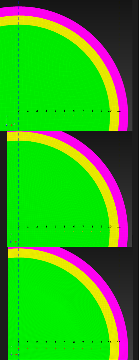
Figure: Tracer numbers [0, 1, 2, ... 11] at distance [0, 1, 2, ... 11] centimeters from point (0, 0, 0) along the x-axis at resolutions sr2c, sr3c, and sr4c (top to bottom, respectively).
Simulation
We created three input decks:
Results
Compute time:
| item | sim | T_sim (ms) | HPC | #proc | cpu time (hh:mm) |
|---|---|---|---|---|---|
| 0 | sr2c.i | 20 | gho | 160 | 00:02 |
| 1 | sr3c.i | 20 | gho | 160 | 00:21 |
| 2 | sr4.i | 20 | att | 160 | 14:00 (est) |
Rigid Body
We verified the rigid body kinematics match those from the voxel mesh, but we don't repeat those time history plots here.
Deformable Body
| resolution | 2 vox/cm | 4 vox/cm | 10 vox/cm |
|---|---|---|---|
| midline |  |  |  |
| displacement | |||
| recipe | displacement_sr2c.yml | displacement_sr3c.yml | displacement_sr4c.yml |
| log strain | |||
| recipe | log_strain_sr2c.yml | log_strain_sr3c.yml | log_strain_sr4c.yml |
| rate of deformation | |||
| recipe | rate_of_deformation_sr2c.yml | rate_of_deformation_sr3c.yml | rate_of_deformation_sr4c.yml |
Figure: Conforming mesh midline section and tracer plots at 1 cm interval along the -axis for displacement magnitude, log strain, and rate of deformation (10,000 Hz acquisition rate, = 0.0001 s).