Conforming versus Segmented Meshes
We define a conforming mesh as a traditional finite element mesh that has nodal placement on the boundary of the geometry approximated by the mesh. A conforming mesh has a piecewise approximation of the curvature on the boundary.
In contrast, a segmented mesh (also known as a voxelized or "sugar-cube" mesh) is composed of voxels that approximate the boundary in a "stair-step" fashion, with nodal placement fixed on a regular, uniform grid of cube-shaped elements. A segmented mesh has a stair-step approximation of the curvature on the boundary.
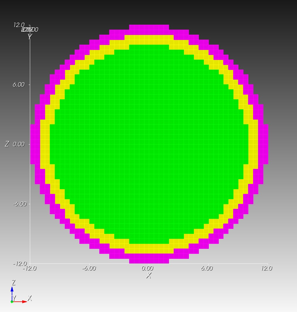
The meshes from the Sphere with Shells section illustrate these two mesh types:
| conforming | segmented |
|---|---|
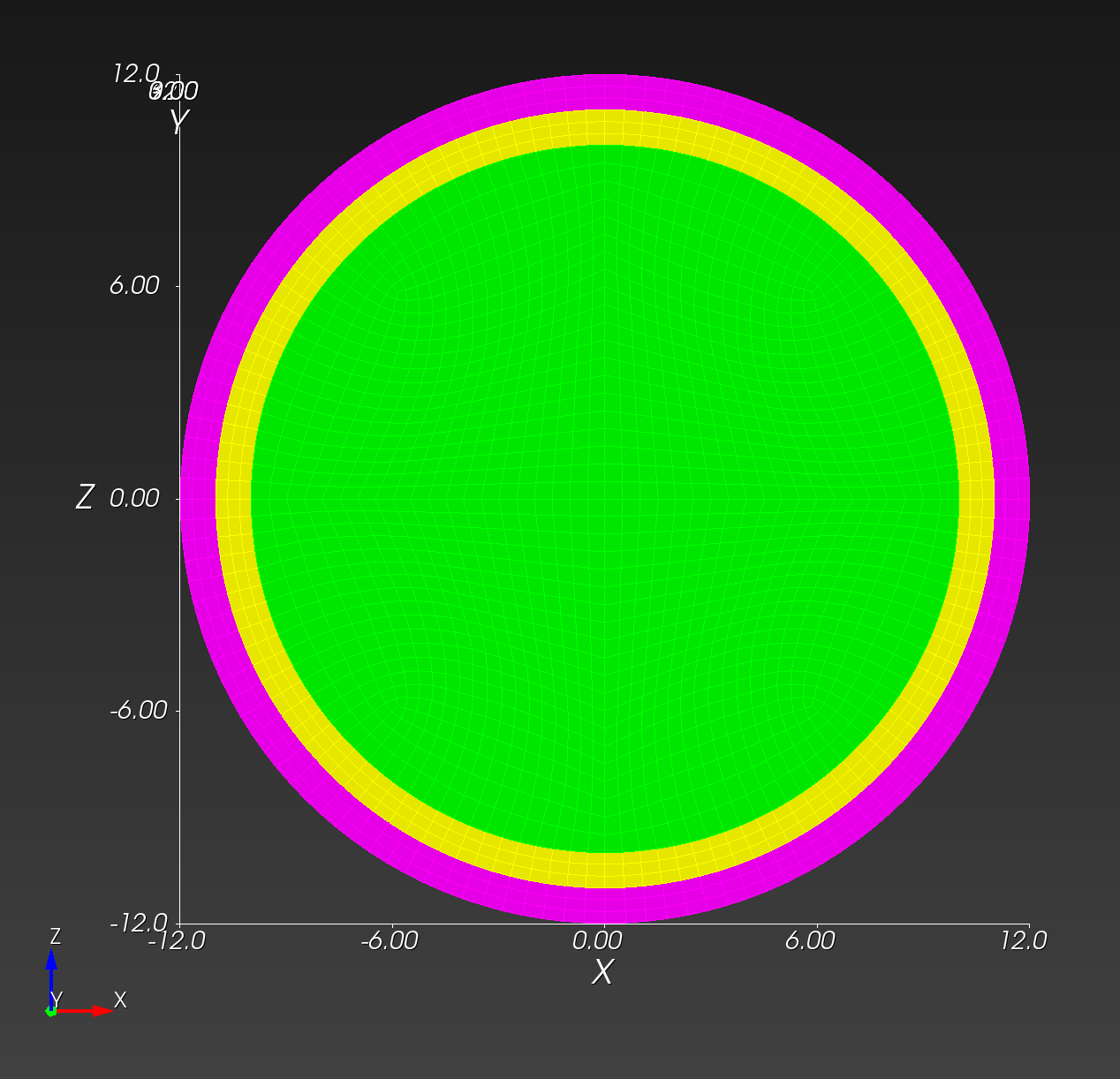 | 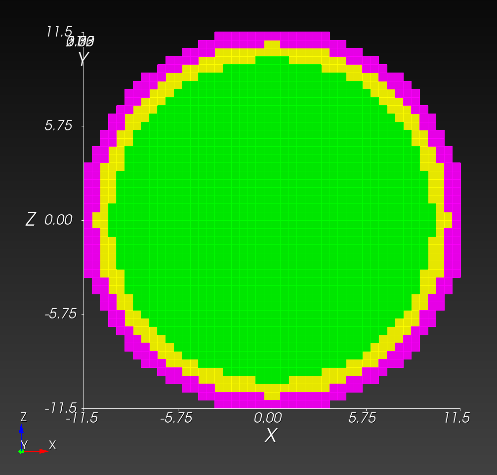 |
 |  |
Both the conforming and segmented meshes approximate the true geometry: a sphere with concentric shells. Both approaches introduce error when used in finite element analysis in the calculation of quantities of interest, such as stress and strain.
We are interested in comparing the two methods, and quantifying what error the segmented approach introduces relative to the conforming approach.
For the spheres with shells example above, we were able to readily create two de novo meshes (the conforming mesh and the segmented mesh). There are instances, however, where a traditional, conforming finite element mesh exists, but a segmented version of the same geometry does not exist.
To create a segmented version of a conforming mesh, we created the segment command. Following are a examples using the segment functionality.
Recovering the Segmented Sphere
We use the conf_0.5cm.g file as our start point. See the Mesh Creation and Visualization section for a download link. Our objective it to recover the segmented version of the model, shown above, using the segment command.
# Clone the .g to .exo
cp conf_0.5cm.g conf_0.5cm.exo

automesh segment hex -i conf_0.5cm.exo -o conf_0.5cm_vox_segmented_g2_s0p5.exo -g 2 -s 0.5
automesh segment hex -i conf_0.5cm.exo -o conf_0.5cm_vox_segmented_g2_s0p5.inp -g 2 -s 0.5
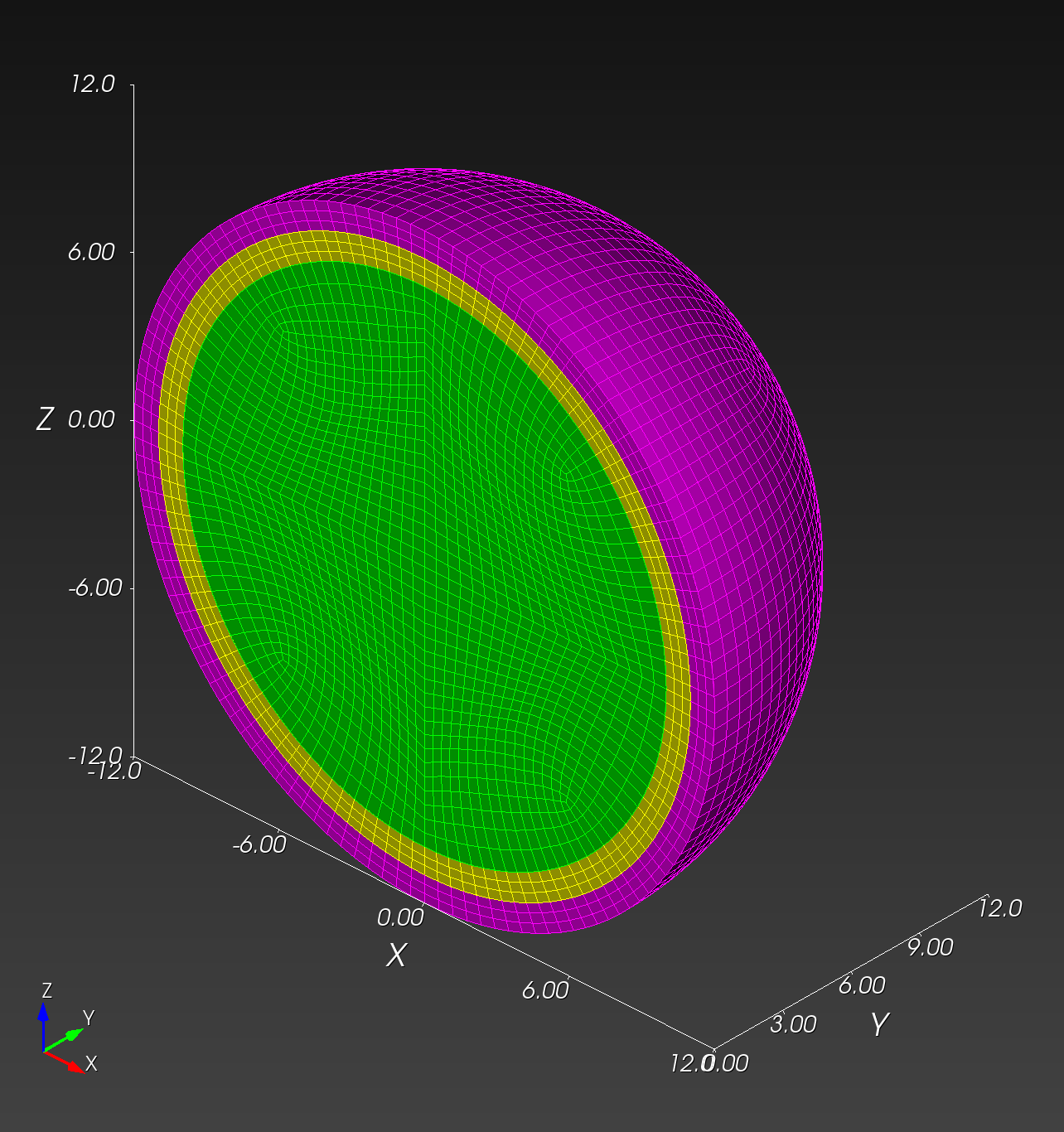
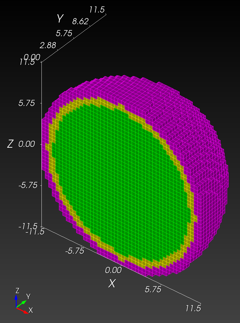
The resulting mesh from conf_0.5cm_segmented_g2_s0p5.exo is shown (with a cut plane to show the interior) below:
| midline | isometric |
|---|---|
 | 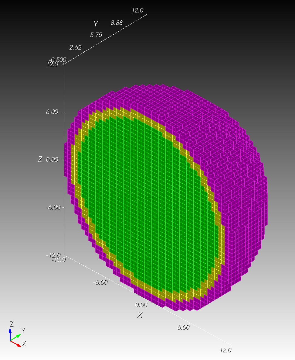 |
The conf_0.5cm_segmented_g2_s0p5.inp file mesh matches conf_0.5cm_segmented_g2_s0p5.exo exactly. Note that these new segmented meshes are slightly different from the original segmentations since they are created from a conforming mesh source.
RMU Brain Model
The RMU brain model, All_Hex_Dec, is a model of a human head.
Source Files
| file | md5 checksum | size |
|---|---|---|
All_Hex_Dec.inp | 4e376f7d551890b807cabc1d89630772 | 212 MB |
All_Hex_Dec.exo | 5df6f584a30139cb89e6e6917f843f55 | 66 MB |
test_1_1.exo | 5c0f02a7960890ffbe536493c4993104 | 95 MB |
test_1_2.exo | db674b42065cd9de9c8eb30ce2945c0f | 13 MB |
test_1_3.exo | 50da29122a0435672e62156308120ea9 | 4 MB |
test_2_1.exo | d108b4fe0aa524610fbe036e337fc6e1 | 105 MB |
test_3_0p8.exo | 60dddb70a9b018b4a25a35850c676eb6 | 205 MB |
test_3_0p8.inp | 63da6d1266a86561209ccda5f69bca23 | 541 MB |
The model has 12 blocks composing the various anatomy of the head and brain, shown below.
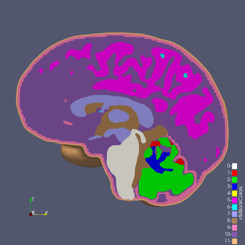
Figure: RMU brain model All_Hex_Dec.exo
With this conforming mesh, we create segmented meshes with the segment command, for example,
automesh segment hex --input All_Hex_Dec.exo --output test_3_0p8.exo --grid 3 --size 0.8e-3
Because All_Hex_Dec.exo and All_Hex_Dec.inp are in units of meters, we specify --size 0.8e-3 to obtain a voxel side length size of 0.8 mm.
The output files have the naming convention test_x_y.exo where
xis the grid number,yis the element length in mm,- and
0p8means0.8 mm.
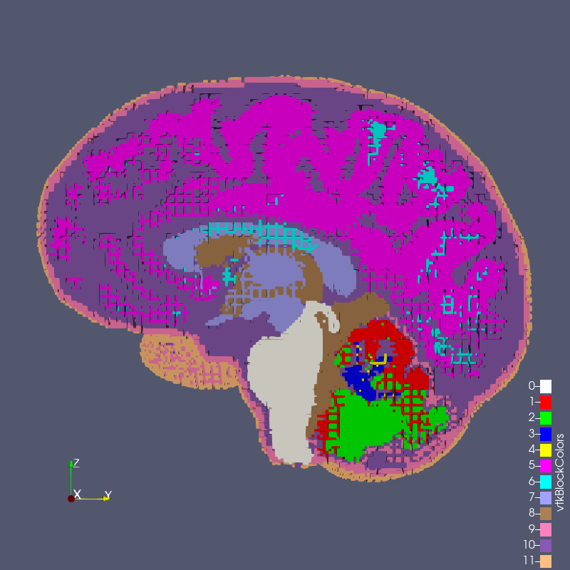
Figure: test_1_1.exo created with options --grid 1 --size 1

Figure: test_1_2.exo created with options --grid 1 --size 2

Figure: test_1_3.exo created with options --grid 1 --size 3
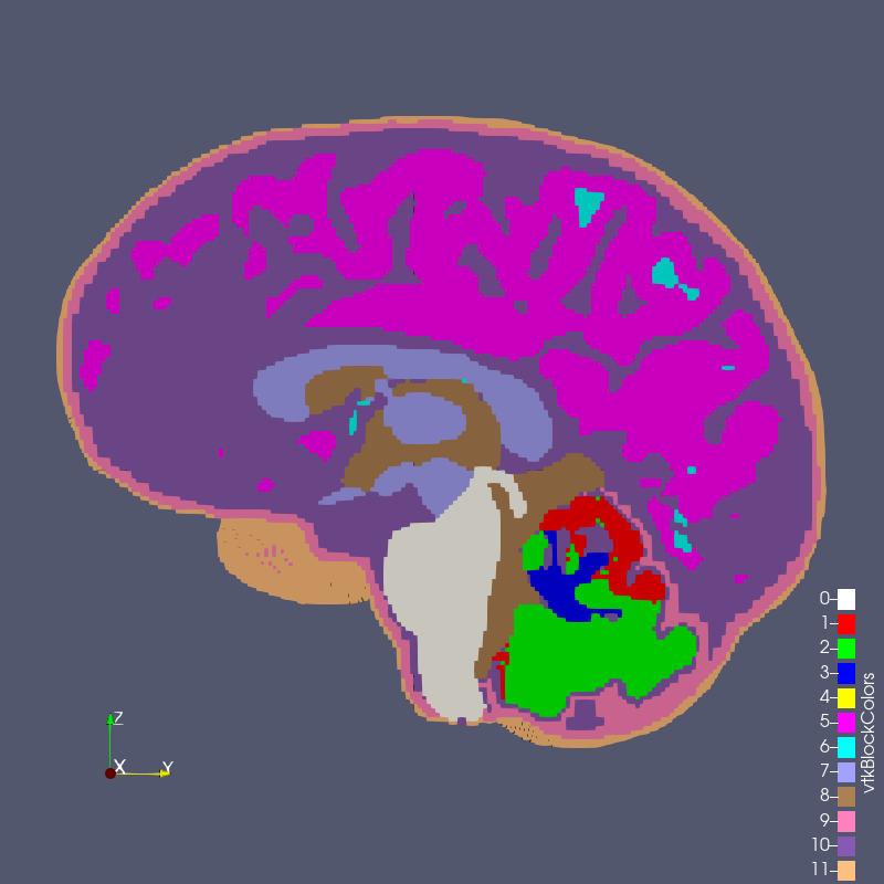
Figure: test_2_1.exo created with options --grid 2 --size 1
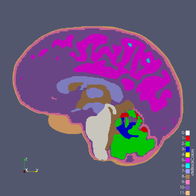
Figure: test_3_0p8.exo created with options --grid 3 --size 0.8
Comparison
All_Hex_Dec.exo | test_3_0p8.exo |
|---|---|
| |